New! Render PlantUML diagrams directly inside GitHub
with our official browser extension —
No server. No tokens. No tracking. Zero permissions but clipboard. —
Try it out and let us know what you think!
Use case diagram
A use case diagram shows how external actors interact with a system: who does what, and which features the system exposes. It's a high-level view of functional requirements, useful early in design to align stakeholders. In PlantUML, you describe actors and use cases in text, and the connections between them. The diagram is generated for you.- Text in, diagram out. Define actors, use cases, and links in a few lines.
- Easy to refactor. Rename an actor or move a use case by editing one line.
- Fits in your repo. Diagrams live next to the code they document, in version control.
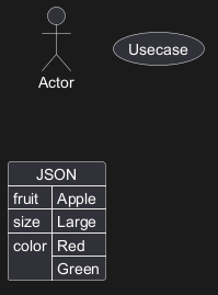
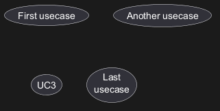
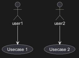
 Usecases
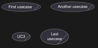
Use cases are enclosed using between parentheses (because two
parentheses looks like an oval).
You can also use the usecase keyword to define a
usecase.
And you can define an alias, using the as keyword.
This alias will be used later, when defining relations.
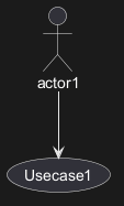
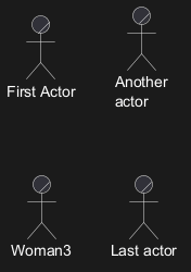
Actors
The name defining an actor is enclosed between colons.
You can also use the actor keyword to define an actor.
An alias can be assigned using the as keyword and can be used later instead of the actor's name, e. g. when defining relations.
You can see from the following examples, that the actor definitions are optional.

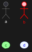
Change Actor style
You can change the actor style from stick man (by default) to:
- an awesome man with the
skinparam actorStyle awesomecommand; - a hollow man with the
skinparam actorStyle hollowcommand.
Stick man (by default)
Awesome man
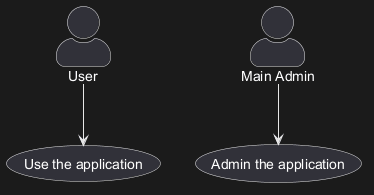
Hollow man
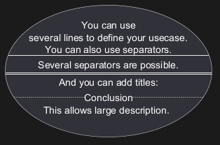
Usecases description
If you want to have a description spanning several lines, you can use quotes.
You can also use the following separators:
--(dashes)..(periods)==(equals)__(underscores)
Use package
You can use packages to group actors or use cases.
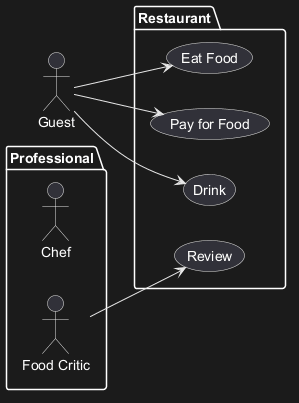
rectangle to change the display of the package.
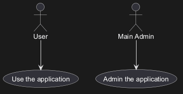
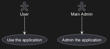
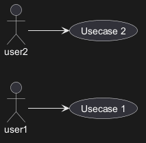
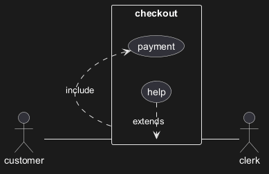
Basic example
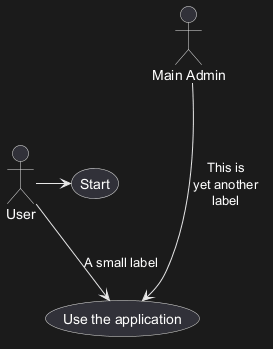
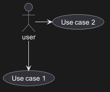
To link actors and use cases, the arrow --> is
used.
The more dashes - in the arrow, the longer the
arrow.
You can add a label on the arrow, by adding a :
character in the arrow definition.
In this example, you see that User has not been defined
before, and is used as an actor.
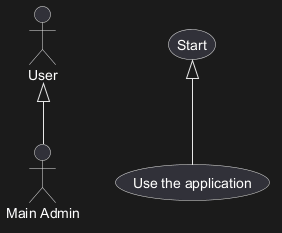
Extension
If one actor/use case extends another one, you can use the symbol <|--.
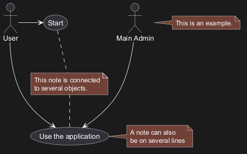
Using notes
You can use the note left of , note right of ,
note top of , note bottom of keywords to
define notes related to a single object.
A note can be also define alone with the note
keywords, then linked to other objects using the .. symbol.
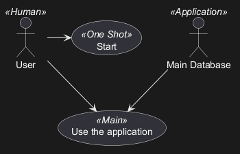
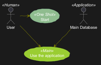
Stereotypes
You can add stereotypes while defining actors and use cases using << and >>.
Changing arrows direction
By default, links between classes have two dashes -- and are vertically oriented.
It is possible to use horizontal link by putting a single dash (or dot) like this:
left, right, up
or down keywords inside the arrow:
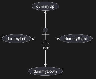
-d- instead of
-down-)
or the two first characters (-do-).
Please note that you should not abuse this functionality : Graphviz gives usually good results without
tweaking.
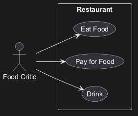
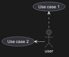
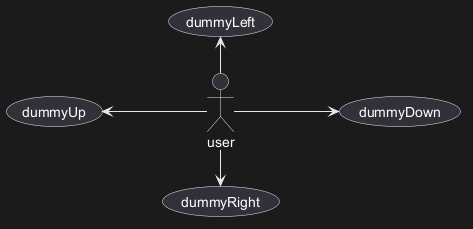
And with the left to right direction parameter:
Splitting diagrams
The newpage keywords to split your diagram into several pages or images.
Left to right direction
The general default behavior when building diagram is top to bottom.
left to right direction command.
The result is often better with this direction.
Skinparam
You can use the skinparam
command to change colors and fonts for the drawing.
You can use this command :
- In the diagram definition, like any other commands,
- In an included file,
- In a configuration file, provided in the command line or the ANT task.
Complete example
Business Use Case
You can add / to make Business Use Case.
Business Usecase
Business Actor
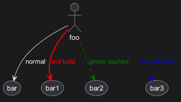
Change arrow color and style (inline style)
You can change the color or style of individual arrows using the inline following notation:
#color;line.[bold|dashed|dotted];text:color
Change element color and style (inline style)
You can change the color or style of individual element using the following notation:
#[color|back:color];line:color;line.[bold|dashed|dotted];text:color
Display JSON Data on Usecase diagram
Simple example