New! Render PlantUML diagrams directly inside GitHub
with our official browser extension —
No server. No tokens. No tracking. Zero permissions but clipboard. —
Try it out and let us know what you think!
Diagramme de déploiement
Un diagramme de déploiement est un type de diagramme qui visualise l'architecture des systèmes, montrant comment les composants logiciels sont déployés sur le matériel. Il fournit une image claire de la distribution des composants sur différents nœuds, tels que les serveurs, les stations de travail et les appareils. Avec PlantUML, la création de diagrammes de déploiement devient un jeu d'enfant. La plateforme offre un moyen simple et intuitif de concevoir ces diagrammes en utilisant du texte simple, assurant des itérations rapides et un contrôle facile des versions. De plus, le forum PlantUML offre une communauté dynamique où les utilisateurs peuvent demander de l'aide, partager des idées et collaborer sur des défis de création de diagrammes. L'un des principaux avantages de PlantUML est sa capacité à s'intégrer de manière transparente à divers outils et plateformes, ce qui en fait un choix privilégié pour les professionnels et les passionnés. Déclarer un élément
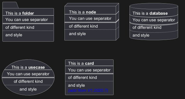
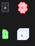
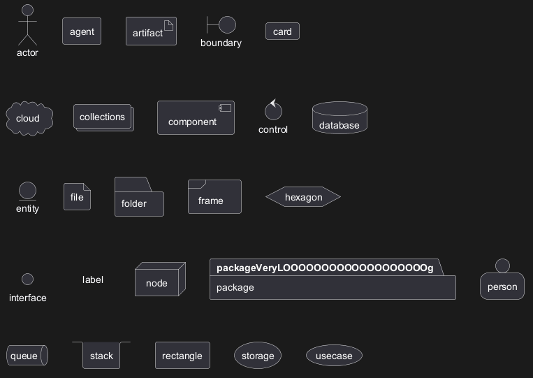
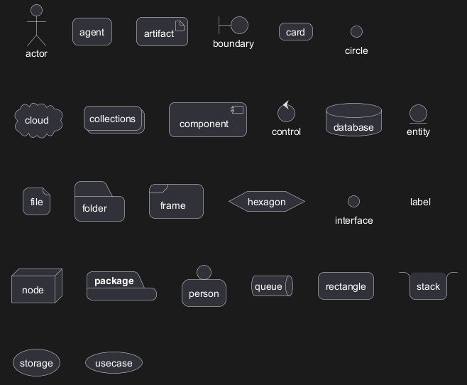
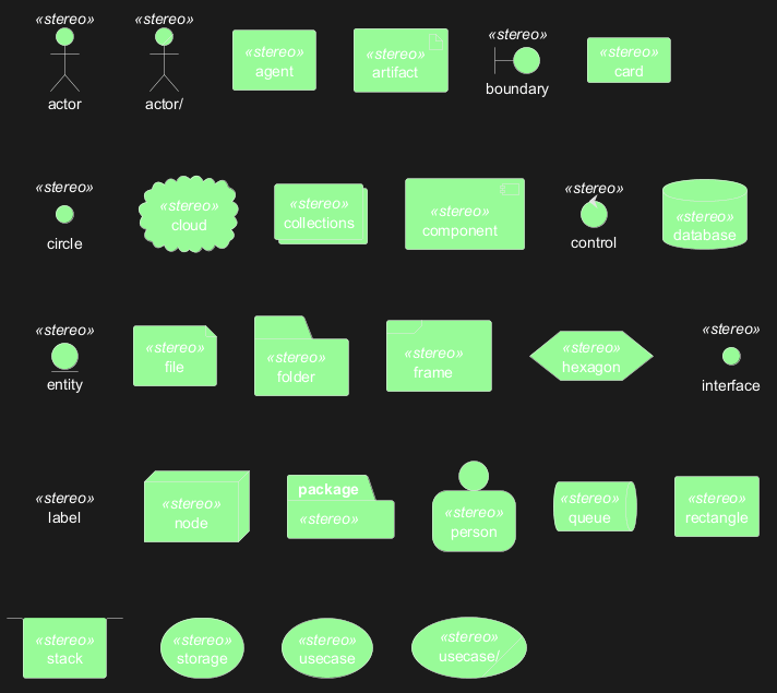
[] pour une longue description.
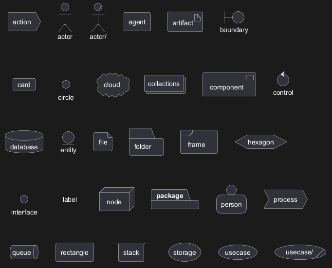
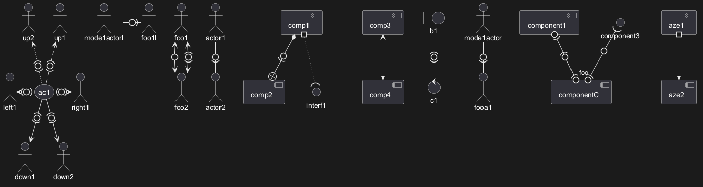
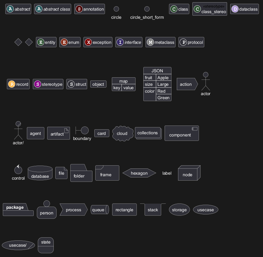
Declaring element (using short form)
We can declare element using some short forms.
| Long form Keyword | Short form Keyword | Long form example | Short form example | Ref. |
actor
|
: a :
|
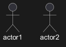
actor actor1
|
:actor2:
|
Actors |
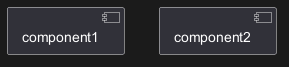
component
|
[ c ]
|
component component1
|
[component2]
|
Components |
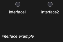
interface
|
() i
|
interface interface1
|
() "interface2"
|
Interfaces |
usecase
|
( u )
|
usecase usecase1
|
(usecase2)
|
Usecases |
Actor
Component
Interface
Usecase
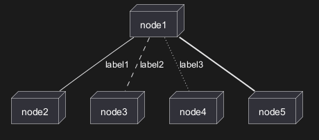
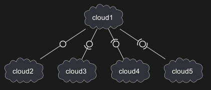
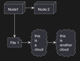
Linking or arrow
You can create simple links between elements with or without labels:
Bracketed arrow style
Similar as Bracketed class relations (linking or arrow) style
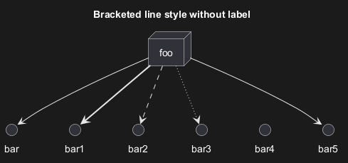
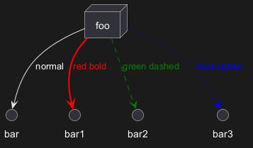
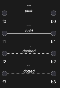
Line style
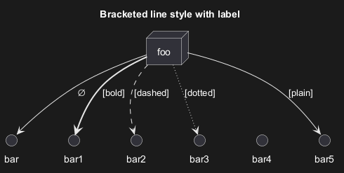
It's also possible to have explicitlybold, dashed, dotted, hidden or plain arrows:- without label
- with label
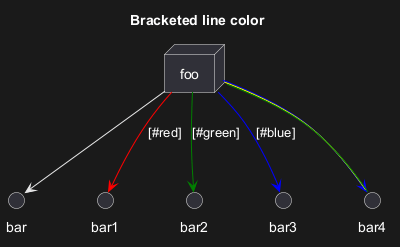
Line color
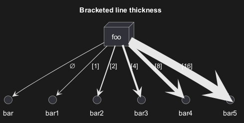
Line thickness
Mix
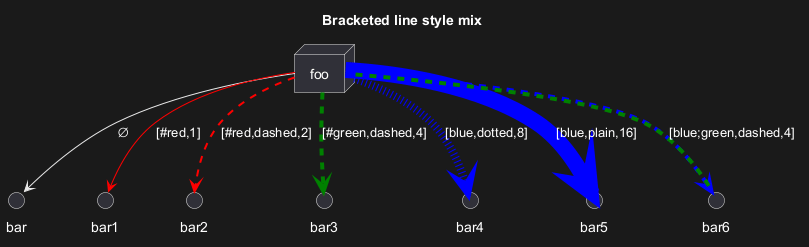
Change arrow color and style (inline style)
You can change the color or style of individual arrows using the inline following notation:
#color;line.[bold|dashed|dotted];text:color
Change element color and style (inline style)
You can change the color or style of individual element using the following notation:
#[color|back:color];line:color;line.[bold|dashed|dotted];text:color
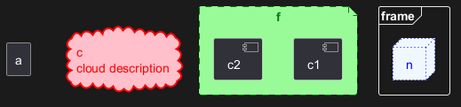
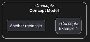
Nestable elements
Here are the nestable elements:

Packages and nested elements
Example with one level

Other example
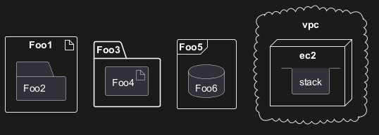
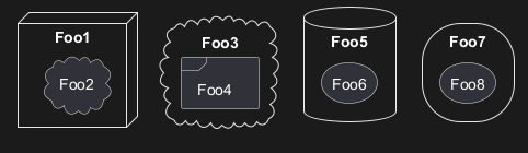
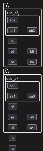
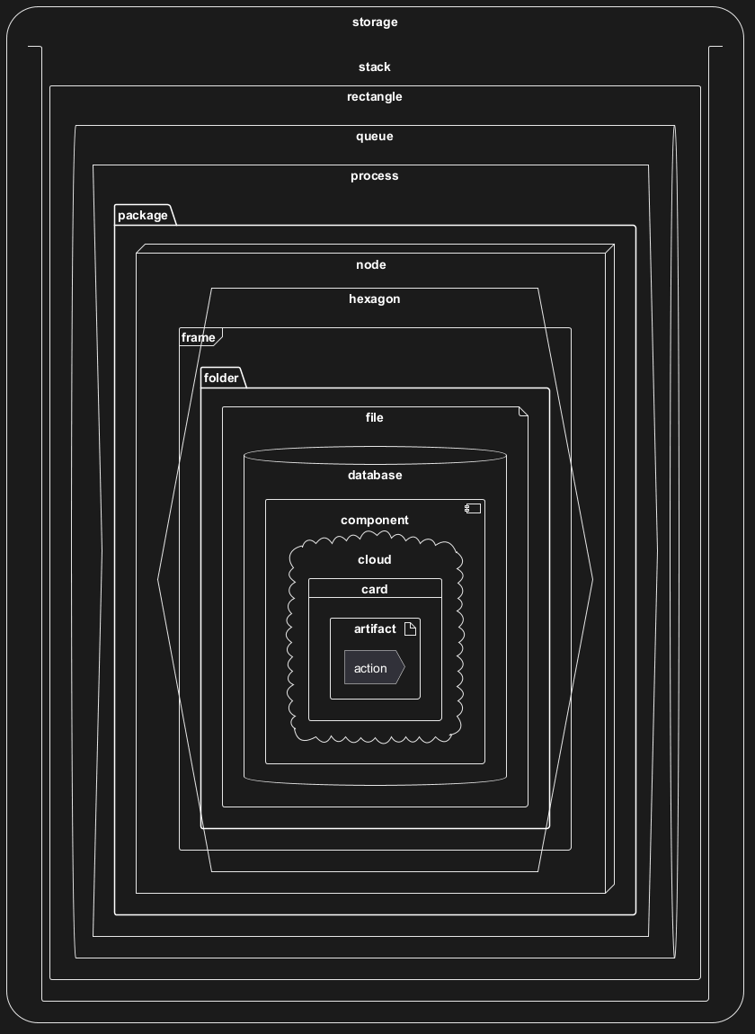
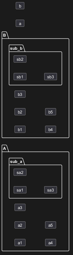
Full nesting
Here is all the nested elements:- by alphabetical order:
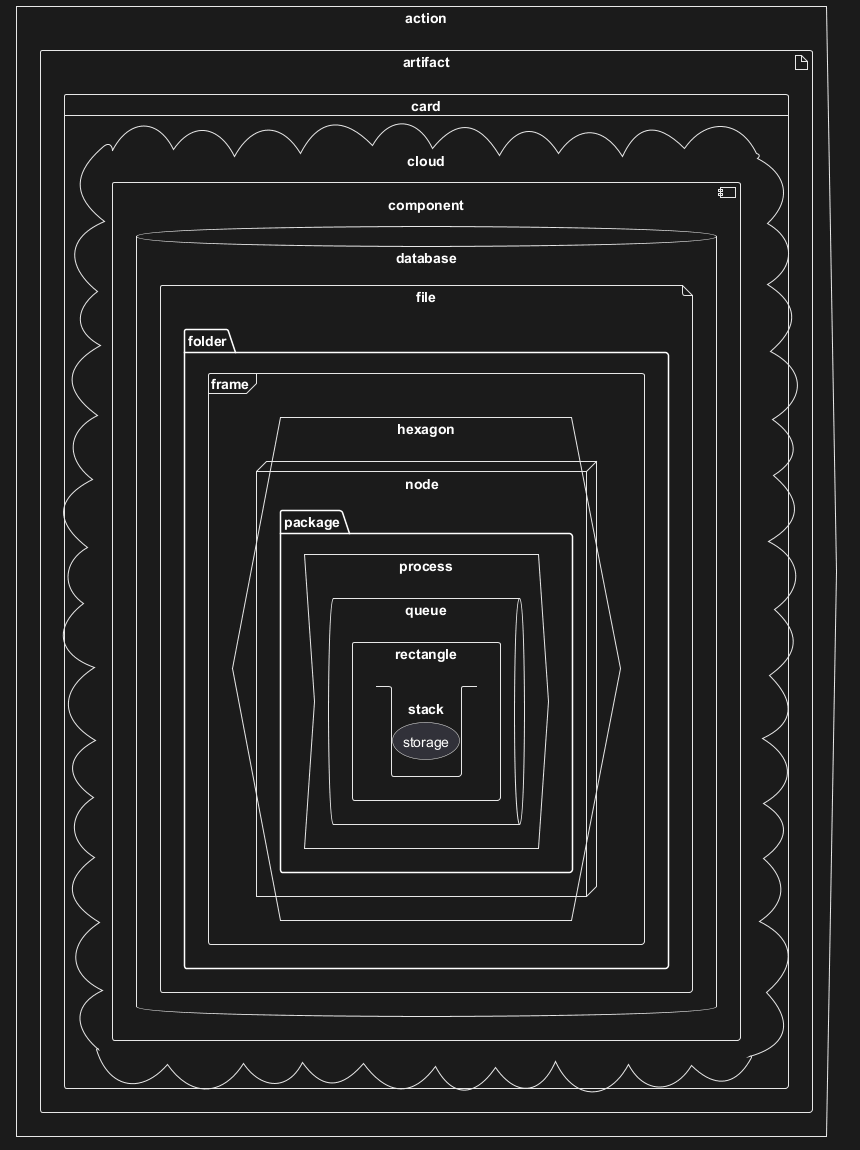
- or reverse alphabetical order
Alias
Simple alias with as
Examples of long alias

Round corner
Specific SkinParameter
roundCorner
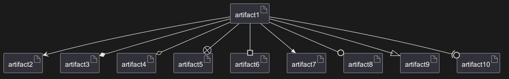
Appendix: All type of arrow line
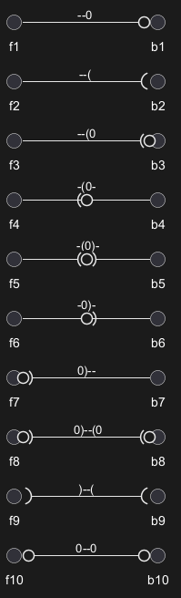
Appendix: All type of arrow head or '0' arrow
Type of arrow head
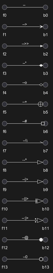
Type of '0' arrow or circle arrow
Appendix: Test of inline style on all element
Simple element
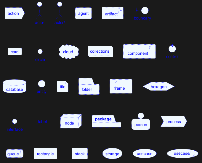
Nested element
Without sub-element

With sub-element

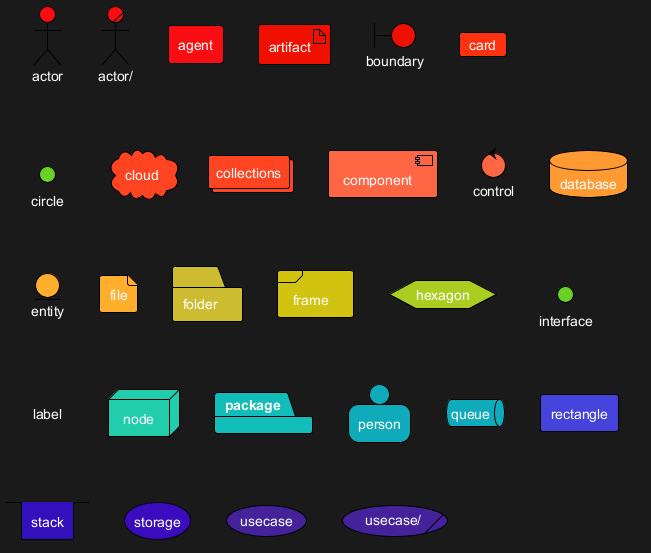
Appendix: Test of style on all element
Simple element
Global style (on componentDiagram)
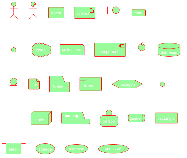
Style for each element
Nested element (without level)
Global style (on componentDiagram)

Style for each nested element

Nested element (with one level)
Global style (on componentDiagram)

Style for each nested element

Appendix: Test of stereotype with style on all element
Simple element
Display JSON Data on Deployment diagram
Simple example
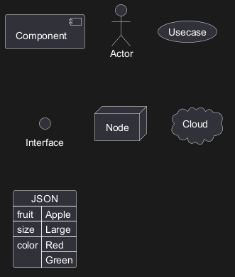
Mixing Deployment (Usecase, Component, Deployment) element within a Class or Object diagram
In order to add a Deployment element or a State element within a Class or Object diagram, you can use the allowmixing or allow_mixing directive.
Mixing all elements
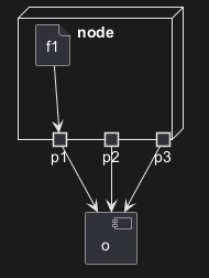
Port [port, portIn, portOut]
You can added port with port, portinand portout keywords.
Port

PortIn
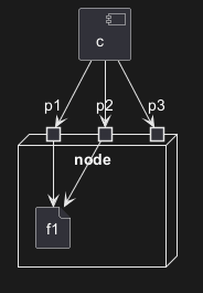
PortOut
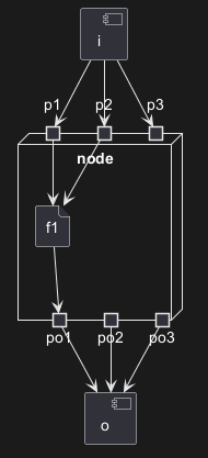
Mixing PortIn & PortOut
Change diagram orientation
You can change (whole) diagram orientation with:
top to bottom direction(by default)left to right direction
Top to bottom (by default)
With Graphviz (layout engine by default)
The main rule is: Nested element first, then simple element.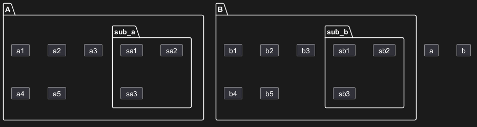
With Smetana (internal layout engine)
The main rule is the opposite: Simple element first, then nested element.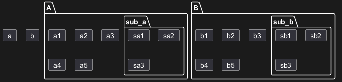
Left to right
With Graphviz (layout engine by default)
With Smetana (internal layout engine)