


New! Render PlantUML diagrams directly inside GitHub
with our official browser extension —
No server. No tokens. No tracking. Zero permissions but clipboard. —
Try it out and let us know what you think!
Diagramme de réseau avec nwdiag
Un diagramme de réseau est une représentation visuelle d'un réseau informatique ou de télécommunications. Il illustre la disposition et les interconnexions des composants du réseau, notamment les serveurs, les routeurs, les commutateurs, les concentrateurs et les périphériques. Les diagrammes de réseau sont des outils précieux pour les ingénieurs et les administrateurs de réseau, qui peuvent ainsi comprendre, configurer et dépanner les réseaux. Ils sont également essentiels pour visualiser la structure et le flux des données dans un réseau, garantissant ainsi des performances et une sécurité optimales. nwdiag, développé par Takeshi Komiya, fournit une plateforme rationalisée pour esquisser rapidement des diagrammes de réseau. Nous remercions Takeshi pour cet outil innovant! Grâce à sa syntaxe intuitive, nwdiag a été intégré de manière transparente dans PlantUML. Les exemples présentés ici sont inspirés de ceux documentés par Takeshi. Diagramme simple
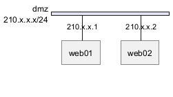
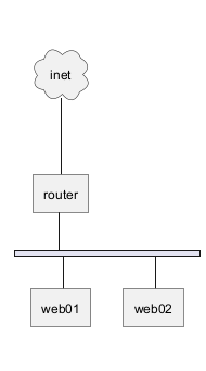
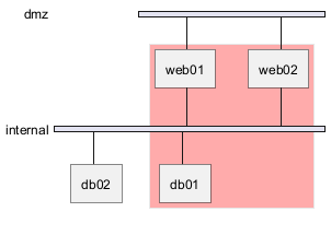
Définir un réseau

Définir certains éléments ou serveurs sur un réseau
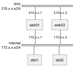
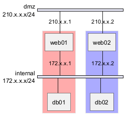
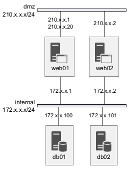
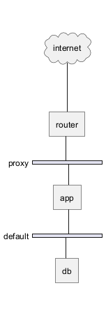
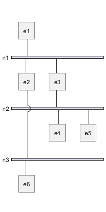
Exemple complet
WARNING
This translation need to be updated. WARNING
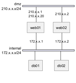
Define multiple addresses
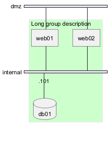
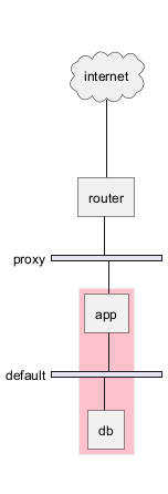
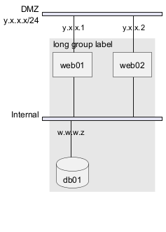
Grouping nodes
Define group inside network definitions
Define group outside of network definitions
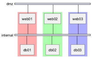
Define several groups on same network
Example with 2 group
Example with 3 groups
Extended Syntax (for network or group)
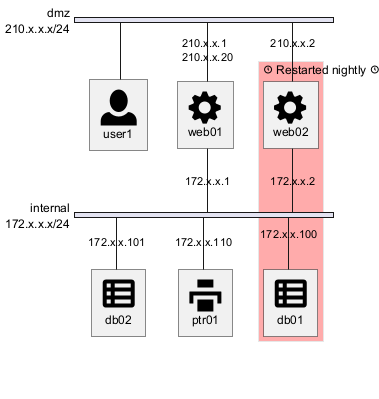
Network
For network or network's component, you can add or change: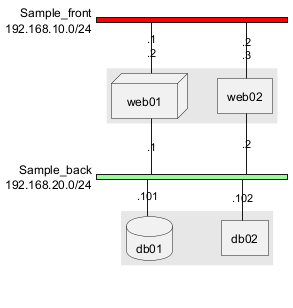
Group
For a group, you can add or change:- color;
- description.
Using Sprites
You can use all sprites (icons) from the Standard Library or any other library.
Use the notation <$sprite> to use a sprite, \n to make a new line, or any other Creole syntax.
Using OpenIconic
You can also use the icons from OpenIconic in network or node descriptions.
Use the notation <&icon> to make an icon, <&icon*n> to multiply the size by a factor n, and \n to make a newline:
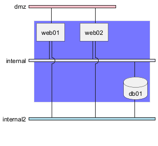
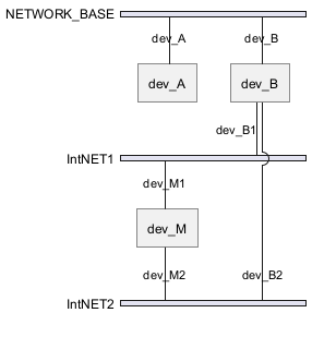
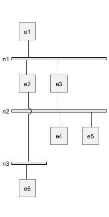
Same nodes on more than two networks
You can use same nodes on different networks (more than two networks); nwdiag use in this case 'jump line' over networks.
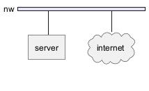
Peer networks
Peer networks are simple connections between two nodes, for which we don't use a horizontal "busbar" network
Peer networks and group
Without group
Group on first
Group on second

Group on third

Add title, caption, header, footer or legend on network diagram

With or without shadow
With shadow (by default)

Without shadow
Change width of the networks
You can change the width of the networks, especially in order to have the same full width for only some or all networks.
Here are some examples, with all the possibilities.
First example
- without

- only the first

- the first and the second

- all the network (with same full width)
Second example
- without
- only the first
- the first and the second
- all the network (with same full width)
Other internal networks
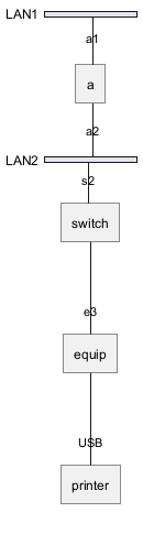
You can define other internal networks (TCP/IP, USB, SERIAL,...).
- Without address or type
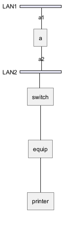
- With address or type
Using (global) style
Without style (by default)
With style
You can use style to change rendering of elements.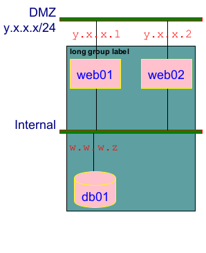
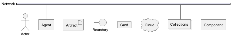
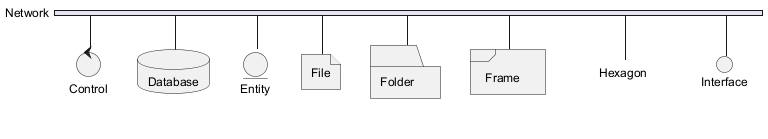
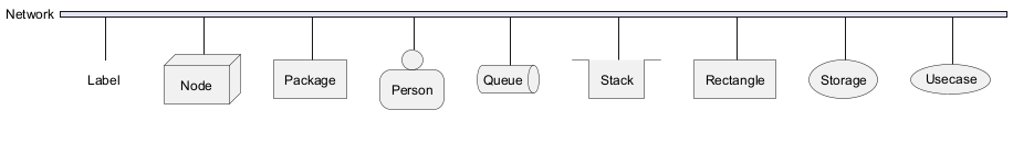
Appendix: Test of all shapes on Network diagram (nwdiag)
FIXME
- Overlap of label for folder
- Hexagon shape is missing
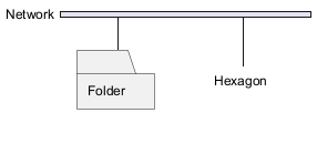
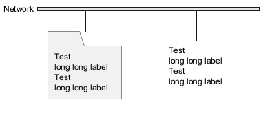
FIXME