


New! Render PlantUML diagrams directly inside GitHub
with our official browser extension —
No server. No tokens. No tracking. Zero permissions but clipboard. —
Try it out and let us know what you think!
Network Diagram with nwdiag
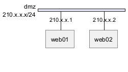
A network diagram is a visual representation of a computer or telecommunications network. It illustrates the arrangement and interconnections of network components, including servers, routers, switches, hubs, and devices. Network diagrams are invaluable tools for network engineers and administrators to understand, set up, and troubleshoot networks. They are also essential for visualizing the structure and flow of data in a network, ensuring optimal performance and security. nwdiag, developed by Takeshi Komiya, provides a streamlined platform to swiftly sketch network diagrams. We extend our gratitude to Takeshi for this innovative tool! Given its intuitive syntax, nwdiag has been seamlessly integrated into PlantUML. The examples showcased here are inspired by the ones documented by Takeshi. Simple diagram
Define a network
To make the process more efficient, it is now possible to bypass thenwdiag { ... } wrapper. You can define your network directly within the PlantUML tags.
Standard approach:


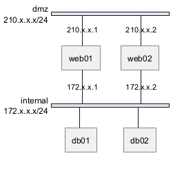
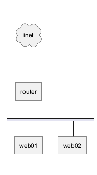
Define some elements or servers on a network
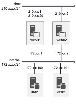
Full example
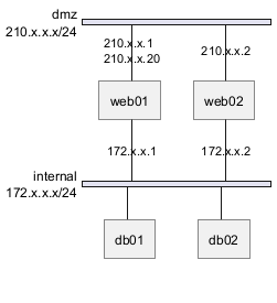
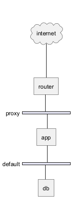
Define multiple addresses
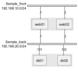
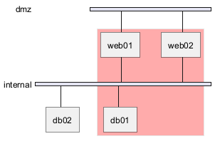
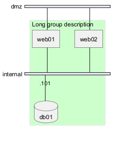
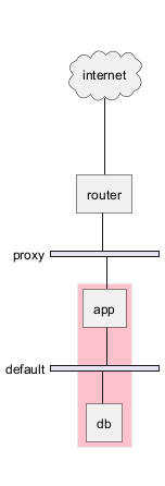
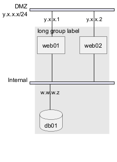
Grouping nodes
Define group inside network definitions
Define group outside of network definitions
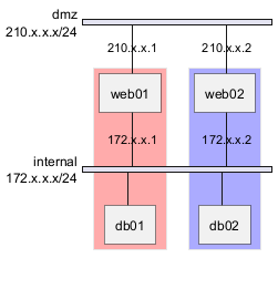
Define several groups on same network
Example with 2 group
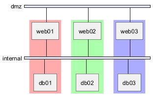
Example with 3 groups
Extended Syntax (for network or group)
Network
For network or network's component, you can add or change: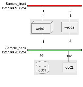
Group
For a group, you can add or change:- color;
- description.
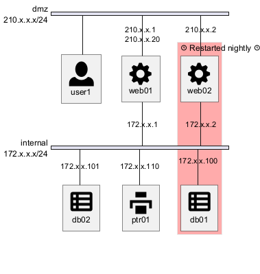
Using Sprites
You can use all sprites (icons) from the Standard Library or any other library.
Use the notation <$sprite> to use a sprite, \n to make a new line, or any other Creole syntax.
Using OpenIconic
You can also use the icons from OpenIconic in network or node descriptions.
Use the notation <&icon> to make an icon, <&icon*n> to multiply the size by a factor n, and \n to make a newline:
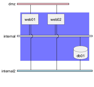
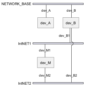
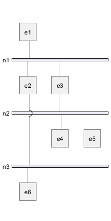
Same nodes on more than two networks
You can use same nodes on different networks (more than two networks); nwdiag use in this case 'jump line' over networks.
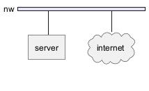
Peer networks
Peer networks are simple connections between two nodes, for which we don't use a horizontal "busbar" network
Peer networks and group
Without group
Group on first
Group on second

Group on third

Add title, caption, header, footer or legend on network diagram

With or without shadow
With shadow (by default)

Without shadow
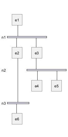
Change width of the networks
You can change the width of the networks, especially in order to have the same full width for only some or all networks.
Here are some examples, with all the possibilities.
First example
- without

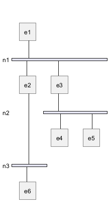
- only the first

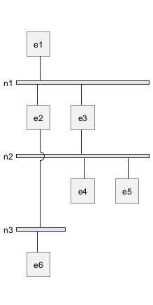
- the first and the second

- all the network (with same full width)
Second example
- without
- only the first
- the first and the second
- all the network (with same full width)
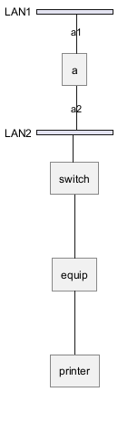
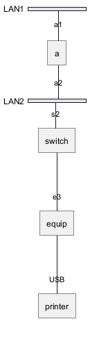
Other internal networks
You can define other internal networks (TCP/IP, USB, SERIAL,...).
- Without address or type
- With address or type
Using (global) style
Without style (by default)
With style
You can use style to change rendering of elements.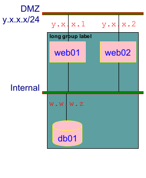
Appendix: Test of all shapes on Network diagram (nwdiag)
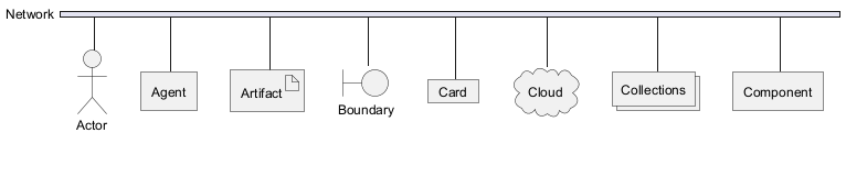
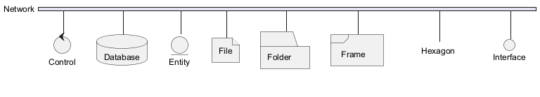
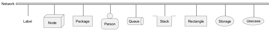
FIXME
- Overlap of label for folder
- Hexagon shape is missing
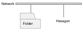
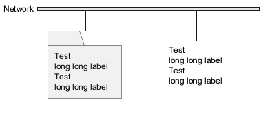
FIXME