


New! Render PlantUML diagrams directly inside GitHub
with our official browser extension —
No server. No tokens. No tracking. Zero permissions but clipboard. —
Try it out and let us know what you think!
使用 nwdiag 的网络图
网络图是计算机或电信网络的直观表示。它说明了网络组件(包括服务器、路由器、交换机、集线器和设备)的排列和互连。网络图是网络工程师和管理员了解、设置和排除网络故障的宝贵工具。 nwdiag 由Takeshi Komiya 开发,为快速绘制 网络图提供了一个精简的平台。我们对 Takeshi 开发的这一创新工具表示感谢! 由于其直观的语法,nwdiag已无缝集成到PlantUML 中。这里展示的示例受到了Takeshi 所记录示例的启发。 简单图示
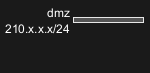
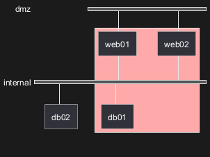
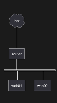
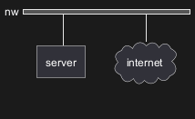
简单图示
定义一个网络

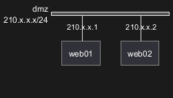
定义网络中的一些元素或服务器
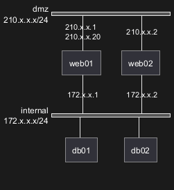
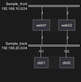
完整的例子
WARNING
This translation need to be updated. WARNING
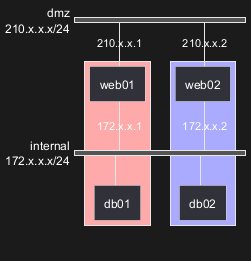
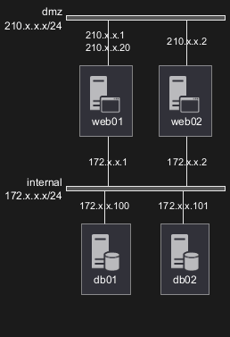
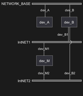
定义多个地址
WARNING
This translation need to be updated. WARNING
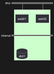
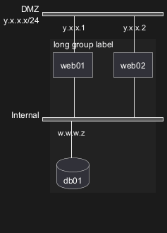
群节点
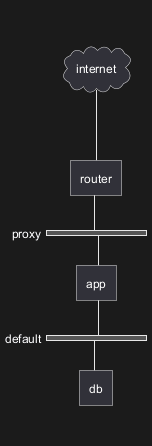
在网络定义中定义组
在网络定义之外定义组
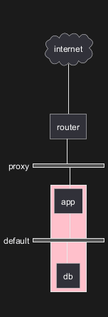
在同一个网络上定义不同的一些组
一个定义了两个组的例子
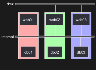
定义了三个组的例子
WARNING
This translation need to be updated. WARNING
拓展语法 (适用于组或者网络)
网络
用于网络或者网络的组成部分,你可以添加或者修改: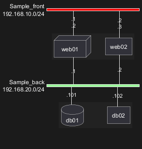
组
对于组,你可以添加或修改:- 颜色;
- 描述.
WARNING
This translation need to be updated. WARNING
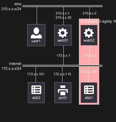
Using Sprites
You can use all sprites (icons) from the Standard Library or any other library.
Use the notation <$sprite> to use a sprite, \n to make a new line, or any other Creole syntax.
Using OpenIconic
You can also use the icons from OpenIconic in network or node descriptions.
Use the notation <&icon> to make an icon, <&icon*n> to multiply the size by a factor n, and \n to make a newline:
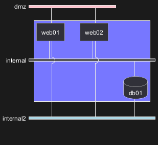
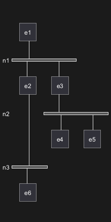
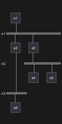
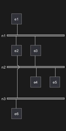
Same nodes on more than two networks
You can use same nodes on different networks (more than two networks); nwdiag use in this case 'jump line' over networks.
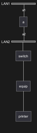
Peer networks
Peer networks are simple connections between two nodes, for which we don't use a horizontal "busbar" network
Peer networks and group
Without group
Group on first

Group on second
Group on third

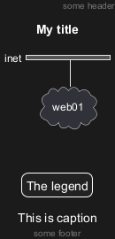
Add title, caption, header, footer or legend on network diagram
With or without shadow
With shadow (by default)

Without shadow
Change width of the networks
You can change the width of the networks, especially in order to have the same full width for only some or all networks.
Here are some examples, with all the possibilities.
First example
- without

- only the first

- the first and the second
- all the network (with same full width)

Second example
- without
- only the first
- the first and the second

- all the network (with same full width)
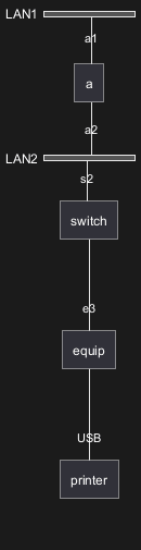
Other internal networks
You can define other internal networks (TCP/IP, USB, SERIAL,...).
- Without address or type
- With address or type
Using (global) style
Without style (by default)
With style
You can use style to change rendering of elements.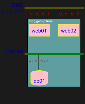
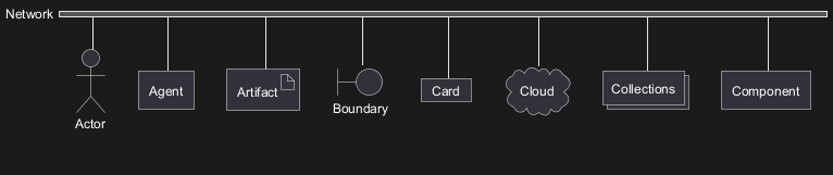
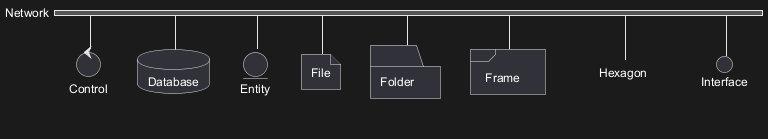
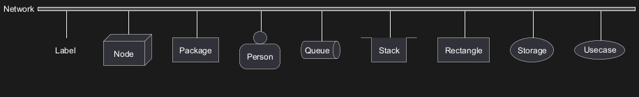
Appendix: Test of all shapes on Network diagram (nwdiag)
FIXME
- Overlap of label for folder
- Hexagon shape is missing
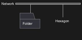
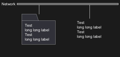
FIXME